9 3.3 Wave Behavior
Behavior of Light
Light waves across the electromagnetic spectrum behave in similar ways. When a light wave encounters an object, it is either transmitted, reflected, absorbed, refracted, polarized, diffracted, or scattered depending on the composition of the object and the wavelength of the light.
Absorption, Transmission, and Reflection
This video reviews the concepts of absorption, transmission, and reflection of light:
Diffraction, Scattering, and Refraction
Diffraction is the bending and spreading of waves around an obstacle. It is most pronounced when a light wave strikes an object with a size comparable to its own wavelength. In the case of visible light, the separation of wavelengths through diffraction results in a rainbow. The figure below shows the grooves on a CD diffracting visible light and producing iridescent colors.

Scattering occurs when light bounces off an object in a variety of directions. The amount of scattering that takes place depends on the wavelength of the light and the size and structure of the object.
The sky appears blue because of this scattering behavior. Light at shorter wavelengths—blue and violet—is scattered by nitrogen and oxygen as it passes through the atmosphere. Longer wavelengths of light—red and yellow—transmit through the atmosphere. This scattering of light at shorter wavelengths illuminates the skies with light from the blue and violet end of the visible spectrum. Even though violet is scattered more than blue, the sky looks blue to us because our eyes are more sensitive to blue light.
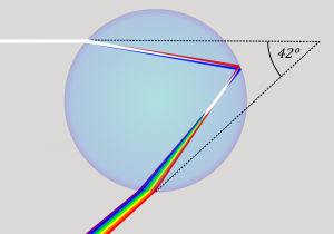
Refraction is when light waves change direction as they pass from one medium to another. Light travels slower in air than in a vacuum, and even slower in water. As light travels into a different medium, the change in speed bends the light. Different wavelengths of light are slowed at different rates, which causes them to bend at different angles. For example, when the full spectrum of visible light travels through the glass of a prism, or through a raindrop, the wavelengths are separated into the colors of the rainbow.

We will discuss refraction in more detail and introduce polarization of light in the sections below. These concepts are especially important for understanding techniques in optical mineralogy and petrology.
Guided Inquiry
Refractive Index
Electromagnetic energy travels at the speed of light, c, in a vacuum. However, when electromagnetic waves travel through matter, they slow down. The speed at which they travel through a material is specific to the density and composition of the material.
The refractive index of a material characterizes the relationship between the speed of light in a vacuum and the speed of light in that material.
The refractive index of a material is defined as:
![]()
where n is the refractive index, c is the speed of light in a vacuum, and v is the observed speed of light in the material. Since the speed of light in matter is always less than c, the index of refraction is always greater than or equal to one.
This table lists some examples of refractive indices of different materials:
| Refractive Indices of Materials | |
| Material | n |
| Air (0 Celsius, 1 atm) | 1.000293 |
| Water, fresh | 1.333 |
| Glass, crown | 1.52 |
| Quartz | 1.544 |
| Zircon | 1.923 |
| Diamond | 2.419 |
Guided Inquiry
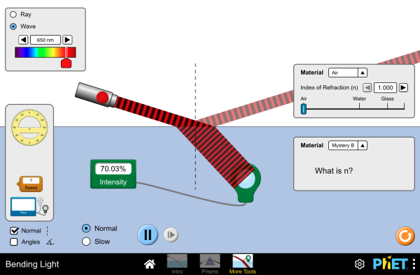
The amount that a light ray changes its direction depends both on the incident angle and the amount that the speed changes. For a ray at a given incident angle, a large change in speed causes a large change in direction and thus a large change in angle. The exact mathematical relationship is the law of refraction, or Snell’s law, after the Dutch mathematician Willebrord Snell (1591–1626), who discovered it in 1621. The law of refraction is stated in equation form as:
![]()
Here n1 and n2 are the indices of refraction for media 1 and 2, and θ1 and θ2 are the angles between the rays and the perpendicular in media 1 and 2. The incoming ray is called the incident ray, the outgoing ray is called the refracted ray, and the associated angles are the incident angle and the refracted angle, respectively.

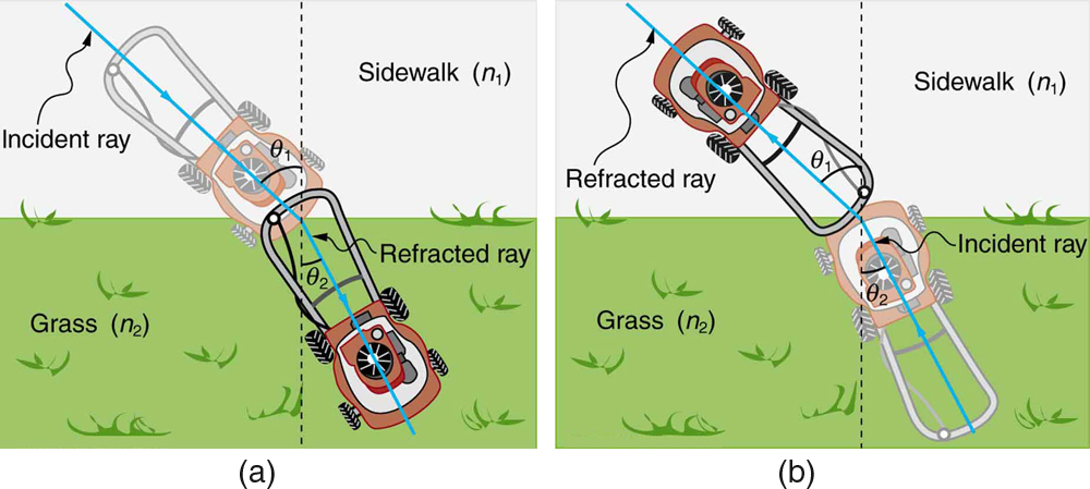
Figure 2.3.9 shows how a ray of light changes direction when it passes from one medium to another. The angles are measured relative to a perpendicular to the surface at the point where the light ray crosses it. (Some of the incident light will be reflected from the surface, but for now we will concentrate on the light that is transmitted.) The change in direction of the light ray depends on how the speed of light changes. The change in the speed of light is related to the indices of refraction of the media involved. In the situations shown in Figure 2.3.9 medium 2 has a greater index of refraction than medium 1. This means that the speed of light is less in medium 2 than in medium 1.
Note that as shown in Figure 2.3.9(a), the direction of the ray moves closer to the perpendicular when it slows down. Conversely, as shown in Figure 2.3.9(b), the direction of the ray moves away from the perpendicular when it speeds up. The path is exactly reversible.
In both cases, you can imagine what happens by thinking about pushing a lawn mower from a footpath onto grass, and vice versa. Going from the footpath to grass, the front wheels are slowed and pulled to the side as shown. This is the same change in direction as for light when it goes from a fast medium to a slow one. When going from the grass to the footpath, the front wheels can move faster and the mower changes direction as shown. This, too, is the same change in direction as for light going from slow to fast.
Guided Inquiry
Properties of Light
The speed of light (electromagnetic energy) in a vacuum is a constant value: c = 3.00 x 10⁸ m/s. However, we will see below that electromagnetic energy slows down when it travels through matter, including minerals.
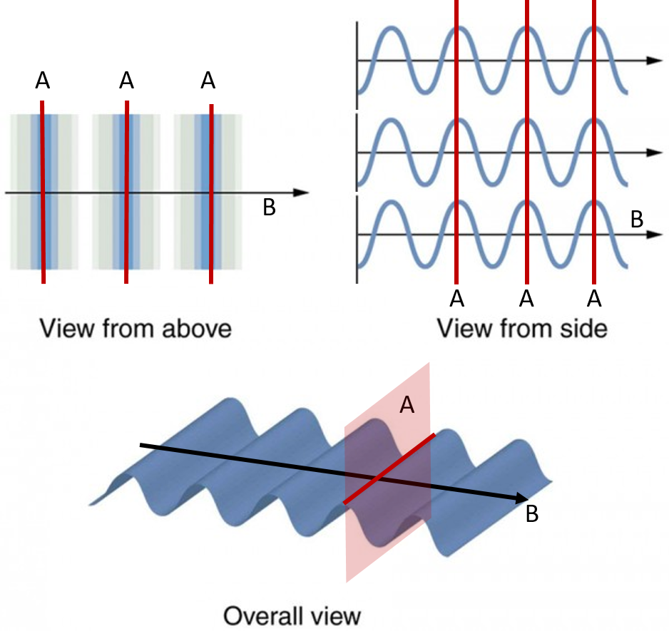
Knowing the propagation direction or direction of travel is important if we wish to understand how light moves through the microscope and our samples. The diagram below shows three views of an electromagnetic wave. In each view , a light ray pointing parallel to the direction of propagation and the wavefront perpendicular to the propagation direction are shown.

Guided Inquiry
Electromagnetic


