
2.2: Coordinate Systems and Components of a Vector
Learning Objectives
By the end of this section, you will be able to:
- Describe vectors in two and three dimensions in terms of their components, using unit vectors along the axes.
- Distinguish between the vector components of a vector and the scalar components of a vector.
- Explain how the magnitude of a vector is defined in terms of the components of a vector.
- Identify the direction angle of a vector in a plane.
- Explain the connection between polar coordinates and Cartesian coordinates in a plane.
Vectors are usually described in terms of their components in a coordinate system. Even in everyday life we naturally invoke the concept of orthogonal projections in a rectangular coordinate system. For example, if you ask someone for directions to a particular location, you will more likely be told to go 40 km east and 30 km north than 50 km in the direction [latex]37\text{°}[/latex] north of east.
In a rectangular (Cartesian) xy-coordinate system in a plane, a point in a plane is described by a pair of coordinates (x, y). In a similar fashion, a vector [latex]\stackrel{\to }{A}[/latex] in a plane is described by a pair of its vector coordinates. The x-coordinate of vector [latex]\stackrel{\to }{A}[/latex] is called its x-component and the y-coordinate of vector [latex]\stackrel{\to }{A}[/latex] is called its y-component. The vector x-component is a vector denoted by [latex]{\stackrel{\to }{A}}_{x}[/latex]. The vector y-component is a vector denoted by [latex]{\stackrel{\to }{A}}_{y}[/latex]. In the Cartesian system, the x and y vector components of a vector are the orthogonal projections of this vector onto the x- and y-axes, respectively. In this way, following the parallelogram rule for vector addition, each vector on a Cartesian plane can be expressed as the vector sum of its vector components:
As illustrated in (Figure), vector [latex]\stackrel{\to }{A}[/latex] is the diagonal of the rectangle where the x-component [latex]{\stackrel{\to }{A}}_{x}[/latex] is the side parallel to the x-axis and the y-component [latex]{\stackrel{\to }{A}}_{y}[/latex] is the side parallel to the y-axis. Vector component [latex]{\stackrel{\to }{A}}_{x}[/latex] is orthogonal to vector component [latex]{\stackrel{\to }{A}}_{y}[/latex].
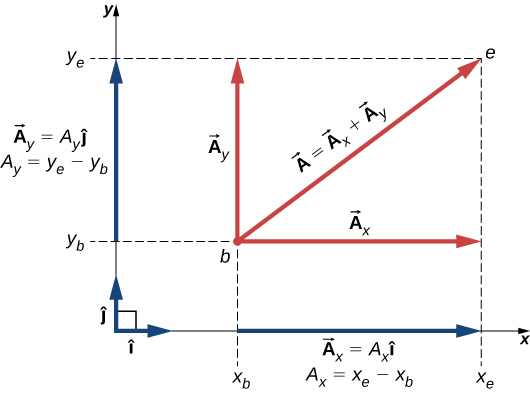
It is customary to denote the positive direction on the x-axis by the unit vector [latex]\hat{i}[/latex] and the positive direction on the y-axis by the unit vector [latex]\hat{j}[/latex]. Unit vectors of the axes, [latex]\hat{i}[/latex] and [latex]\hat{j}[/latex], define two orthogonal directions in the plane. As shown in (Figure), the x- and y- components of a vector can now be written in terms of the unit vectors of the axes:
The vectors [latex]{\stackrel{\to }{A}}_{x}[/latex] and [latex]{\stackrel{\to }{A}}_{y}[/latex] defined by (Figure) are the vector components of vector [latex]\stackrel{\to }{A}[/latex]. The numbers [latex]{A}_{x}[/latex] and [latex]{A}_{y}[/latex] that define the vector components in (Figure) are the scalar components of vector [latex]\stackrel{\to }{A}[/latex]. Combining (Figure) with (Figure), we obtain the component form of a vector:
If we know the coordinates [latex]b({x}_{b},{y}_{b})[/latex] of the origin point of a vector (where b stands for “beginning”) and the coordinates [latex]e({x}_{e},{y}_{e})[/latex] of the end point of a vector (where e stands for “end”), we can obtain the scalar components of a vector simply by subtracting the origin point coordinates from the end point coordinates:
Displacement of a Mouse Pointer
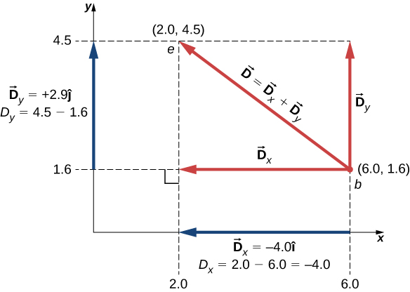
A mouse pointer on the display monitor of a computer at its initial position is at point (6.0 cm, 1.6 cm) with respect to the lower left-side corner. If you move the pointer to an icon located at point (2.0 cm, 4.5 cm), what is the displacement vector of the pointer?
Strategy
The origin of the xy-coordinate system is the lower left-side corner of the computer monitor. Therefore, the unit vector [latex]\hat{i}[/latex] on the x-axis points horizontally to the right and the unit vector [latex]\hat{j}[/latex] on the y-axis points vertically upward. The origin of the displacement vector is located at point b(6.0, 1.6) and the end of the displacement vector is located at point e(2.0, 4.5). Substitute the coordinates of these points into (Figure) to find the scalar components [latex]{D}_{x}[/latex] and [latex]{D}_{y}[/latex] of the displacement vector [latex]\stackrel{\to }{D}[/latex]. Finally, substitute the coordinates into (Figure) to write the displacement vector in the vector component form.
Solution
We identify [latex]{x}_{b}=6.0[/latex], [latex]{x}_{e}=2.0[/latex], [latex]{y}_{b}=1.6[/latex], and [latex]{y}_{e}=4.5[/latex], where the physical unit is 1 cm. The scalar x- and y-components of the displacement vector are
The vector component form of the displacement vector is
This solution is shown in (Figure).
Significance
Notice that the physical unit—here, 1 cm—can be placed either with each component immediately before the unit vector or globally for both components, as in (Figure). Often, the latter way is more convenient because it is simpler.
The vector x-component [latex]{\stackrel{\to }{D}}_{x}=-4.0\hat{i}=4.0(\text{−}\hat{i})[/latex] of the displacement vector has the magnitude [latex]|{\stackrel{\to }{D}}_{x}|=|-4.0||\hat{i}|=4.0[/latex] because the magnitude of the unit vector is [latex]|\hat{i}|=1[/latex]. Notice, too, that the direction of the x-component is [latex]\text{−}\hat{i}[/latex], which is antiparallel to the direction of the +x-axis; hence, the x-component vector [latex]{\stackrel{\to }{D}}_{x}[/latex] points to the left, as shown in (Figure). The scalar x-component of vector [latex]\stackrel{\to }{D}[/latex] is [latex]{D}_{x}=-4.0[/latex].
Similarly, the vector y-component [latex]{\stackrel{\to }{D}}_{y}=+2.9\hat{j}[/latex] of the displacement vector has magnitude [latex]|{\stackrel{\to }{D}}_{y}|=|2.9||\hat{j}|=\phantom{\rule{0.2em}{0ex}}2.9[/latex] because the magnitude of the unit vector is [latex]|\hat{j}|=1[/latex]. The direction of the y-component is [latex]+\hat{j}[/latex], which is parallel to the direction of the +y-axis. Therefore, the y-component vector [latex]{\stackrel{\to }{D}}_{y}[/latex] points up, as seen in (Figure). The scalar y-component of vector [latex]\stackrel{\to }{D}[/latex] is [latex]{D}_{y}=+2.9[/latex]. The displacement vector [latex]\stackrel{\to }{D}[/latex] is the resultant of its two vector components.
The vector component form of the displacement vector (Figure) tells us that the mouse pointer has been moved on the monitor 4.0 cm to the left and 2.9 cm upward from its initial position.
Check Your Understanding 2.4
A blue fly lands on a sheet of graph paper at a point located 10.0 cm to the right of its left edge and 8.0 cm above its bottom edge and walks slowly to a point located 5.0 cm from the left edge and 5.0 cm from the bottom edge. Choose the rectangular coordinate system with the origin at the lower left-side corner of the paper and find the displacement vector of the fly. Illustrate your solution by graphing.
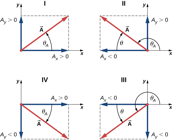
When the vector lies either in the first quadrant or in the fourth quadrant, where component [latex]{A}_{x}[/latex] is positive ((Figure)), the angle [latex]\theta[/latex] in (Figure) is identical to the direction angle [latex]{\theta }_{A}[/latex]. For vectors in the fourth quadrant, angle [latex]\theta[/latex] is negative, which means that for these vectors, direction angle [latex]{\theta }_{A}[/latex] is measured clockwise from the positive x-axis. Similarly, for vectors in the second quadrant, angle [latex]\theta[/latex] is negative. When the vector lies in either the second or third quadrant, where component [latex]{A}_{x}[/latex] is negative, the direction angle is [latex]{\theta }_{A}=\theta +180\text{°}[/latex] ((Figure)).
Magnitude and Direction of the Displacement VectorYou move a mouse pointer on the display monitor from its initial position at point (6.0 cm, 1.6 cm) to an icon located at point (2.0 cm, 4.5 cm). What are the magnitude and direction of the displacement vector of the pointer?
Strategy
In (Figure), we found the displacement vector [latex]\stackrel{\to }{D}[/latex] of the mouse pointer (see (Figure)). We identify its scalar components [latex]{D}_{x}=-4.0\phantom{\rule{0.2em}{0ex}}\text{cm}[/latex] and [latex]{D}_{y}=+2.9\phantom{\rule{0.2em}{0ex}}\text{cm}[/latex] and substitute into (Figure) and (Figure) to find the magnitude D and direction [latex]{\theta }_{D}[/latex], respectively.
Solution
The magnitude of vector [latex]\stackrel{\to }{D}[/latex] is
The direction angle is
Vector [latex]\stackrel{\to }{D}[/latex] lies in the second quadrant, so its direction angle is
Check Your Understanding 2.5
If the displacement vector of a blue fly walking on a sheet of graph paper is [latex]\stackrel{\to }{D}=(-5.00\hat{i}-3.00\hat{j})\text{cm}[/latex], find its magnitude and direction.
In many applications, the magnitudes and directions of vector quantities are known and we need to find the resultant of many vectors. For example, imagine 400 cars moving on the Golden Gate Bridge in San Francisco in a strong wind. Each car gives the bridge a different push in various directions and we would like to know how big the resultant push can possibly be. We have already gained some experience with the geometric construction of vector sums, so we know the task of finding the resultant by drawing the vectors and measuring their lengths and angles may become intractable pretty quickly, leading to huge errors. Worries like this do not appear when we use analytical methods. The very first step in an analytical approach is to find vector components when the direction and magnitude of a vector are known.
Let us return to the right triangle in (Figure). The quotient of the adjacent side [latex]{A}_{x}[/latex] to the hypotenuse A is the cosine function of direction angle [latex]{\theta }_{A}[/latex], [latex]{A}_{x}\text{/}A=\text{cos}\phantom{\rule{0.2em}{0ex}}{\theta }_{A}[/latex], and the quotient of the opposite side [latex]{A}_{y}[/latex] to the hypotenuse A is the sine function of [latex]{\theta }_{A}[/latex], [latex]{A}_{y}\text{/}A=\text{sin}\phantom{\rule{0.2em}{0ex}}{\theta }_{A}[/latex]. When magnitude A and direction [latex]{\theta }_{A}[/latex] are known, we can solve these relations for the scalar components:
When calculating vector components with (Figure), care must be taken with the angle. The direction angle [latex]{\theta }_{A}[/latex] of a vector is the angle measured counterclockwise from the positive direction on the x-axis to the vector. The clockwise measurement gives a negative angle.
Components of Displacement Vectors
A rescue party for a missing child follows a search dog named Trooper. Trooper wanders a lot and makes many trial sniffs along many different paths. Trooper eventually finds the child and the story has a happy ending, but his displacements on various legs seem to be truly convoluted. On one of the legs he walks 200.0 m southeast, then he runs north some 300.0 m. On the third leg, he examines the scents carefully for 50.0 m in the direction [latex]30\text{°}[/latex] west of north. On the fourth leg, Trooper goes directly south for 80.0 m, picks up a fresh scent and turns [latex]23\text{°}[/latex] west of south for 150.0 m. Find the scalar components of Trooper’s displacement vectors and his displacement vectors in vector component form for each leg.
Strategy
Let’s adopt a rectangular coordinate system with the positive x-axis in the direction of geographic east, with the positive y-direction pointed to geographic north. Explicitly, the unit vector [latex]\hat{i}[/latex] of the x-axis points east and the unit vector [latex]\hat{j}[/latex] of the y-axis points north. Trooper makes five legs, so there are five displacement vectors. We start by identifying their magnitudes and direction angles, then we use (Figure) to find the scalar components of the displacements and (Figure) for the displacement vectors.
Solution
On the first leg, the displacement magnitude is [latex]{L}_{1}=200.0\phantom{\rule{0.2em}{0ex}}\text{m}[/latex] and the direction is southeast. For direction angle [latex]{\theta }_{1}[/latex] we can take either [latex]45\text{°}[/latex] measured clockwise from the east direction or [latex]45\text{°}+270\text{°}[/latex] measured counterclockwise from the east direction. With the first choice, [latex]{\theta }_{1}=-45\text{°}[/latex]. With the second choice, [latex]{\theta }_{1}=+315\text{°}[/latex]. We can use either one of these two angles. The components are
The displacement vector of the first leg is
On the second leg of Trooper’s wanderings, the magnitude of the displacement is [latex]{L}_{2}=300.0\phantom{\rule{0.2em}{0ex}}\text{m}[/latex] and the direction is north. The direction angle is [latex]{\theta }_{2}=+90\text{°}[/latex]. We obtain the following results:
On the third leg, the displacement magnitude is [latex]{L}_{3}=50.0\phantom{\rule{0.2em}{0ex}}\text{m}[/latex] and the direction is [latex]30\text{°}[/latex] west of north. The direction angle measured counterclockwise from the eastern direction is [latex]{\theta }_{3}=30\text{°}+90\text{°}=+120\text{°}[/latex]. This gives the following answers:
On the fourth leg of the excursion, the displacement magnitude is [latex]{L}_{4}=80.0\phantom{\rule{0.2em}{0ex}}\text{m}[/latex] and the direction is south. The direction angle can be taken as either [latex]{\theta }_{4}=-90\text{°}[/latex] or [latex]{\theta }_{4}=+270\text{°}[/latex]. We obtain
On the last leg, the magnitude is [latex]{L}_{5}=150.0\phantom{\rule{0.2em}{0ex}}\text{m}[/latex] and the angle is [latex]{\theta }_{5}=-23\text{°}+270\text{°}=+247\text{°}[/latex] [latex](23\text{°}[/latex] west of south), which gives
Check Your Understanding 2.6
If Trooper runs 20 m west before taking a rest, what is his displacement vector?
Polar Coordinates
To describe locations of points or vectors in a plane, we need two orthogonal directions. In the Cartesian coordinate system these directions are given by unit vectors [latex]\hat{i}[/latex] and [latex]\hat{j}[/latex] along the x-axis and the y-axis, respectively. The Cartesian coordinate system is very convenient to use in describing displacements and velocities of objects and the forces acting on them. However, it becomes cumbersome when we need to describe the rotation of objects. When describing rotation, we usually work in the polar coordinate system.
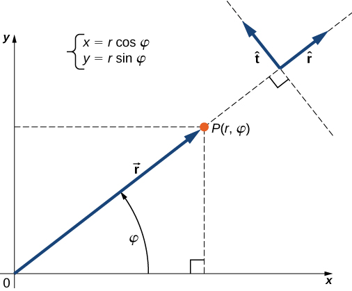
In the polar coordinate system, the location of point P in a plane is given by two polar coordinates ((Figure)). The first polar coordinate is the radial coordinate r, which is the distance of point P from the origin. The second polar coordinate is an angle [latex]\phi[/latex] that the radial vector makes with some chosen direction, usually the positive x-direction. In polar coordinates, angles are measured in radians, or rads. The radial vector is attached at the origin and points away from the origin to point P. This radial direction is described by a unit radial vector [latex]\hat{r}[/latex]. The second unit vector [latex]\hat{t}[/latex] is a vector orthogonal to the radial direction [latex]\hat{r}[/latex]. The positive [latex]+\hat{t}[/latex] direction indicates how the angle [latex]\phi[/latex] changes in the counterclockwise direction. In this way, a point P that has coordinates (x, y) in the rectangular system can be described equivalently in the polar coordinate system by the two polar coordinates [latex](r,\phi)[/latex]. (Figure) is valid for any vector, so we can use it to express the x- and y-coordinates of vector [latex]\stackrel{\to }{r}[/latex]. In this way, we obtain the connection between the polar coordinates and rectangular coordinates of point P:
Polar Coordinates
A treasure hunter finds one silver coin at a location 20.0 m away from a dry well in the direction [latex]20\text{°}[/latex] north of east and finds one gold coin at a location 10.0 m away from the well in the direction [latex]20\text{°}[/latex] north of west. What are the polar and rectangular coordinates of these findings with respect to the well?
Strategy
The well marks the origin of the coordinate system and east is the +x-direction. We identify radial distances from the locations to the origin, which are [latex]{r}_{S}=20.0\phantom{\rule{0.2em}{0ex}}\text{m}[/latex] (for the silver coin) and [latex]{r}_{G}=10.0\phantom{\rule{0.2em}{0ex}}\text{m}[/latex] (for the gold coin). To find the angular coordinates, we convert [latex]20\text{°}[/latex] to radians: [latex]20\text{°}=\pi 20\text{/}180=\pi \text{/}9[/latex]. We use (Figure) to find the x- and y-coordinates of the coins.
Solution
The angular coordinate of the silver coin is [latex]{\phi }_{S}=\pi \text{/}9[/latex], whereas the angular coordinate of the gold coin is [latex]{\phi }_{G}=\pi -\pi \text{/}9=8\pi \text{/}9[/latex]. Hence, the polar coordinates of the silver coin are [latex]({r}_{S},{\phi }_{S})=(20.0\phantom{\rule{0.2em}{0ex}}\text{m},\pi \text{/}9)[/latex] and those of the gold coin are [latex]({r}_{G},{\phi }_{G})=(10.0\phantom{\rule{0.2em}{0ex}}\text{m},8\pi \text{/}9)[/latex]. We substitute these coordinates into (Figure) to obtain rectangular coordinates. For the gold coin, the coordinates are
For the silver coin, the coordinates are
Vectors in Three Dimensions
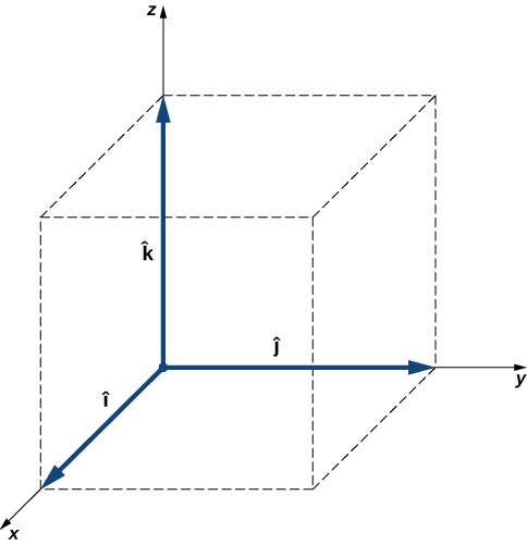
To specify the location of a point in space, we need three coordinates (x, y, z), where coordinates x and y specify locations in a plane, and coordinate z gives a vertical position above or below the plane. Three-dimensional space has three orthogonal directions, so we need not two but three unit vectors to define a three-dimensional coordinate system. In the Cartesian coordinate system, the first two unit vectors are the unit vector of the x-axis [latex]\hat{i}[/latex] and the unit vector of the y-axis [latex]\hat{j}[/latex]. The third unit vector [latex]\hat{k}[/latex] is the direction of the z-axis ((Figure)). The order in which the axes are labeled, which is the order in which the three unit vectors appear, is important because it defines the orientation of the coordinate system. The order x-y-z, which is equivalent to the order [latex]\hat{i}[/latex] - [latex]\hat{j}[/latex] - [latex]\hat{k}[/latex], defines the standard right-handed coordinate system (positive orientation).
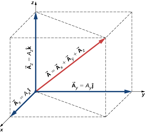
In three-dimensional space, vector [latex]\stackrel{\to }{A}[/latex] has three vector components: the x-component [latex]{\stackrel{\to }{A}}_{x}={A}_{x}\hat{i}[/latex], which is the part of vector [latex]\stackrel{\to }{A}[/latex] along the x-axis; the y-component [latex]{\stackrel{\to }{A}}_{y}={A}_{y}\hat{j}[/latex], which is the part of [latex]\stackrel{\to }{A}[/latex] along the y-axis; and the z-component [latex]{\stackrel{\to }{A}}_{z}={A}_{z}\hat{k}[/latex], which is the part of the vector along the z-axis. A vector in three-dimensional space is the vector sum of its three vector components ((Figure)):
If we know the coordinates of its origin [latex]b({x}_{b},{y}_{b},{z}_{b})[/latex] and of its end [latex]e({x}_{e},{y}_{e},{z}_{e})[/latex], its scalar components are obtained by taking their differences: [latex]{A}_{x}[/latex] and [latex]{A}_{y}[/latex] are given by (Figure) and the z-component is given by
Magnitude A is obtained by generalizing (Figure) to three dimensions:
This expression for the vector magnitude comes from applying the Pythagorean theorem twice. As seen in (Figure), the diagonal in the xy-plane has length [latex]\sqrt{{A}_{x}^{2}+{A}_{y}^{2}}[/latex] and its square adds to the square [latex]{A}_{z}^{2}[/latex] to give [latex]{A}^{2}[/latex]. Note that when the z-component is zero, the vector lies entirely in the xy-plane and its description is reduced to two dimensions.
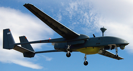
Takeoff of a Drone
During a takeoff of IAI Heron ((Figure)), its position with respect to a control tower is 100 m above the ground, 300 m to the east, and 200 m to the north. One minute later, its position is 250 m above the ground, 1200 m to the east, and 2100 m to the north. What is the drone’s displacement vector with respect to the control tower? What is the magnitude of its displacement vector?
Strategy
We take the origin of the Cartesian coordinate system as the control tower. The direction of the +x-axis is given by unit vector [latex]\hat{i}[/latex] to the east, the direction of the +y-axis is given by unit vector [latex]\hat{j}[/latex] to the north, and the direction of the +z-axis is given by unit vector [latex]hat{k}[/latex], which points up from the ground. The drone’s first position is the origin (or, equivalently, the beginning) of the displacement vector and its second position is the end of the displacement vector.
Solution
We identify b(300.0 m, 200.0 m, 100.0 m) and e(480.0 m, 370.0 m, 250.0m), and use (Figure) and (Figure) to find the scalar components of the drone’s displacement vector:
We substitute these components into (Figure) to find the displacement vector:
We substitute into (Figure) to find the magnitude of the displacement:
Check Your Understanding 2.7
If the average velocity vector of the drone in the displacement in (Figure) is [latex]\stackrel{\to }{u}=(15.0\hat{i}+31.7\hat{j}+2.5\hat{k})\text{m}\text{/}\text{s}[/latex], what is the magnitude of the drone’s velocity vector?
Reading Check:
